If you've ever wondered how experts in software development bring their ideas to life, Unified Modeling Language (UML) diagrams are a big part of the answer. The best part? UML diagrams are not just for experts. No matter how complex, they can benefit anyone trying to design, develop, or explain a software project. Read on and dive in!
Let's get started by exploring easy-to-understand UML diagram examples. These diagrams come from the Templates Community of EdrawMax. Whether you're a newcomer to UML or looking for inspiration for your next project, these diagrams will help you grasp the concepts easily.
As a dedicated diagram maker, Wondershare EdrawMax supports 280+ types of diagrams and offers 15,000+ ready-made templates. Download it and visit the templates community to find the one most suitable for you.
In this article
- UML Sequence Diagram
- UML Class Diagram
- UML Database Diagram
- UML Deployment Diagram
- UML Communication Diagram
- UML Diagram of Supermarkets
- UML Activity Diagram
- UML State Diagram
- UML Timing Diagram
- UML Package Diagram
- UML Interaction Diagram
- School Enrollment UML Activity Diagram
- UML Component Diagram
- UML Diagram for Java
- Student Registration UML Diagram
- UML Object Diagram
- Hospital Management UML Diagram
- Library System UML Diagram
- Component Diagram in UML
- UML Dependency Diagram
- How To Customize a UML Diagram
- Conclusion
UML Sequence Diagram
UML Sequence Diagrams, for example, show how operations are carried out. They record the interaction of objects in a collaborative situation. Sequence Diagrams are time-focused and visually describe the interaction order by representing time and messages delivered and received on the diagram's vertical axis.

 below.
  below.
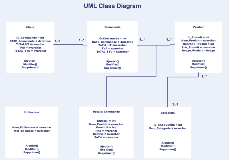
 UML Class Diagram
This is a UML class diagram for a domain model. Managers can deliver functionality relating to certain entities and hold crucial instances of these entities, such as the current article and the current user. UML class diagrams can be used to create data models for information systems, among other things.

UML Database Diagram
This UML database diagram displays some data access classes from Spring and Hibernate. A UML database diagram has the following advantages:

UML Deployment Diagram
A deployment diagram is a type of UML diagram that illustrates the execution architecture of a system, with nodes such as hardware or software execution environments and the middleware that links them. Deployment diagrams are frequently used to describe a system's physical hardware and software. It can be used to determine how the system will be installed physically on the hardware.

UML Communication Diagram
UML communication diagrams, like sequence diagrams, are a sort of interaction diagram that shows how objects interact. A communication diagram is a subset of an object diagram representing both the objects and the communications between them. The communication diagram displays the messages that objects send to one another and the relationships between them.

UML Diagram of Supermarkets
This UML diagram template is a powerful visual representation of a supermarket's operation. It provides a clear and simplified overview of the various components and processes involved in a supermarket's daily operations. One of the strengths of this UML diagram is its simplicity, making it easy for readers to understand the flow of activities within a supermarket.

UML Activity Diagram
A UML activity diagram is a flowchart that shows how information moves from one action to the next. A system operation can be used to describe the action. The control flow is shown from one action to the next. This flow can be sequential, branched, or running concurrently. In activity diagrams, numerous elements such as fork, join, and others are utilized to deal with flow control.

UML State Diagram
This UML state diagram, also known as the UML state chart, demonstrates the account life cycle of the online buying process. It's a computer science application of the mathematical concept of a finite automaton rendered in Unified Modeling Language (UML) notation.

UML Timing Diagram
UML Timing diagrams intend to portray interactions where the primary objective of the diagram is to reason about time. Timing diagrams focus on changing conditions within and between lifelines along a linear time axis. They represent the behavior of individual classifiers and classifier associations, focusing on the timing of events that generate changes in the lifelines' modeled circumstances.

UML Package Diagram
Package diagrams are structural diagrams that depict the arrangement and packaging of model pieces. A package is a group of linked UML elements, including diagrams, documents, classes, and other packages. Each component is arranged hierarchically inside the package, analogous to a folder in the figure.

UML Interaction Diagram
By its very name, an interaction diagram is a type of UML diagram created to record the collaborative efforts of a system's components. Message flows within a system can be described using interaction diagrams, setting the stage for one or more lifelines. UML's interaction diagrams can also show real-time data and depict the ordered events within a system.

School Enrollment UML Activity Diagram
EdrawMax can generate a UML activity diagram for registering for classes. The UML diagram for enrolling in dance class begins with the student filling out a registration form to ensure they meet the prerequisites. If accepted, the student starts classes and pays the dancing school's first tuition.

UML Component Diagram
Object-oriented systems' physical components can be represented in diagram form using UML Component diagrams. Component-based systems are easier to visualize, describe, and document with their help, and they can be engineered both forward and backward to produce executable systems. Component diagrams are a type of class diagram used to illustrate a system's static implementation by isolating its individual parts.

UML Diagram for Java
A Java UML diagram is a static structural diagram showing how a system is put together, including all its components, classes, properties, operations, and object relationships. UML's strong support for object-oriented programming makes it a natural fit for Java-based projects. Class names, characteristics, relationships, and even certain methods are included in the diagram.

Student Registration UML Diagrame
This section of an object diagram illustrates Mary Jones, a student, and the classes she has signed up for. The Student Registration UML Diagram includes link objects representing associations in a class diagram. Actors use cases and their interconnections are all depicted here.

UML Object Diagram
Object diagrams are used in the Unified Modeling Language (UML) to portray a system's structure at a particular moment. In the Unified Modeling Language (UML), an object diagram highlights a subset of objects, their properties, and their connections. Foretelling the future of any arbitrary representation of a system is possible by correlating a collection of object diagrams.

Hospital Management UML Diagram
This UML diagram was drawn to aid developers in making a hospital administration system. Attributes, methods, and associations between classes are all covered. These details guarantee that your hospital management system is built to perform as you expect. Conceptual modeling of the static image of a software application and detailed modeling of translating models into programming code are two common uses for Hospital Management UML diagrams.

Library System UML Diagram
The main actors in the library management system, as well as the activities they perform and the objects they interact with, are depicted in this UML diagram. Information stored in library management systems will now be simpler to comprehend, update, maintain, and record. UML diagrams were used to illustrate the library management system project.

Component Diagram in UML
In UML, a component diagram is used to partition a complex object-oriented system into more understandable parts. It stands for the node's physical representation of the system, including its components, files, libraries, etc. Components, interfaces, dependencies, aggregations, constraints, generalizations, associations, and realizations are only a few typical nodes and edges that make up a UML component diagram.

UML Dependency Diagram
The most generic relationship between two packages, classes, or objects is dependency, represented by a dashed arrow: A depends on B if modifications to B may demand changes to A. Usage is a UML dependency in which one named element (client) requires another named element (supply) for its full specification or implementation.

How To Customize a UML Diagram
Now that you've explored some fantastic UML diagram examples, let's dive into the fun part: customizing your UML diagrams. This section will introduce you to EdrawMax, a versatile and user-friendly diagramming tool, to simplify this process. It's like a magic wand for creating and customizing UML diagrams and so much more. It's designed to make complex things simple.

Step-by-Step Guide
EdrawMax makes it easy to make a UML diagram. Using the free diagram creator, you may do a variety of things, such as import data from a.csv file or start from scratch using pre-made charts. Here's how you can use it to create your personalized UML diagrams:
Step 1Download EdrawMax
Download, install, launch EdrawMax. Log in with a Wondershare ID or an account of Google, Facebook, or Twitter.
Step 2Open Your File
On the homepage, go to Open to find the eddx file you have downloaded. Or, you may go to the Templates section to find more templates.
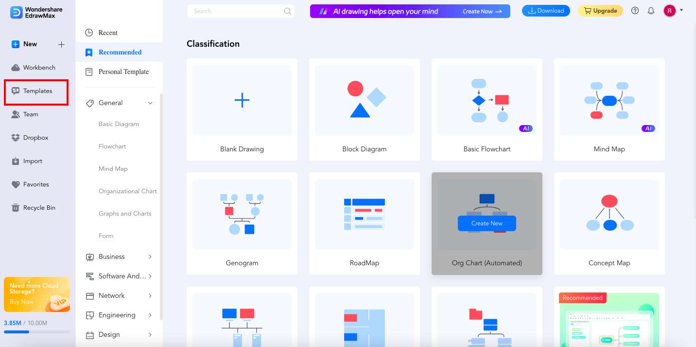
Step3Select Another Template
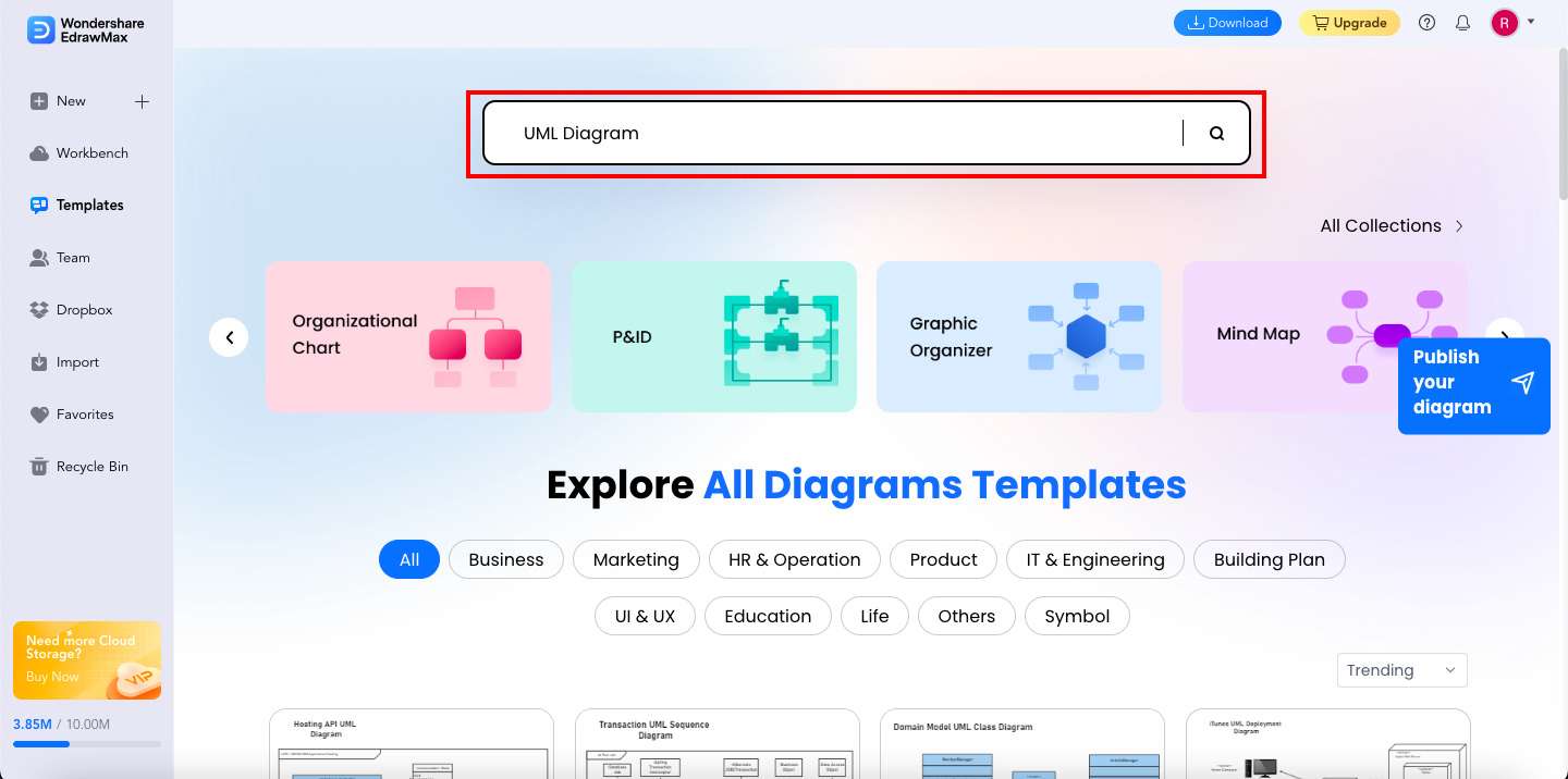
Once you're in EdrawMax's Templates Community, type in the type of template you need in the search bar and press Enter on your keyboard. Look for a UML diagram that best suits your needs and preferences. Whether for software design, system analysis, or anything in between, EdrawMax has got you covered.
Step 4Use the Template
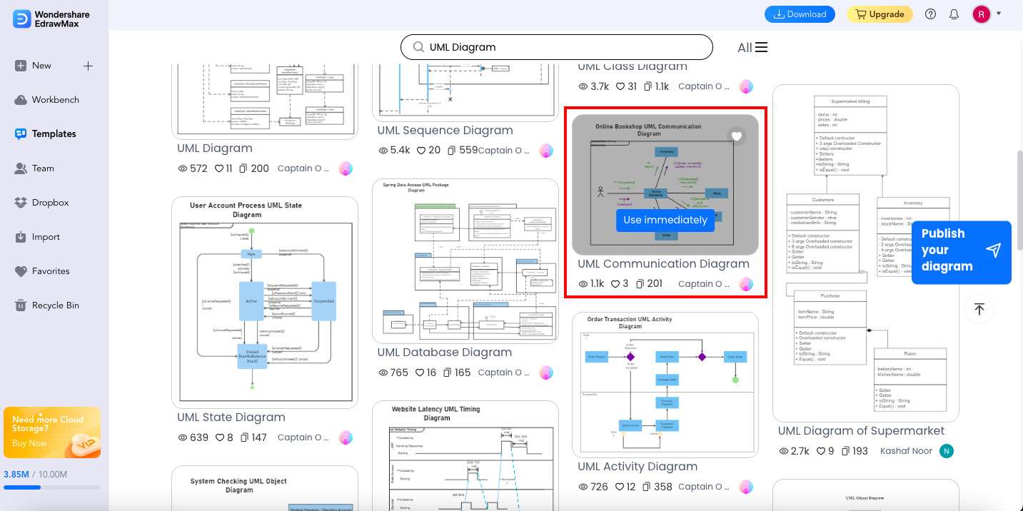
Move your mouse cursor over the template once you've chosen one, then click Use immediately. A pop-up message will then appear. Click Create to access your chosen template.
Step 5Customize the Diagram
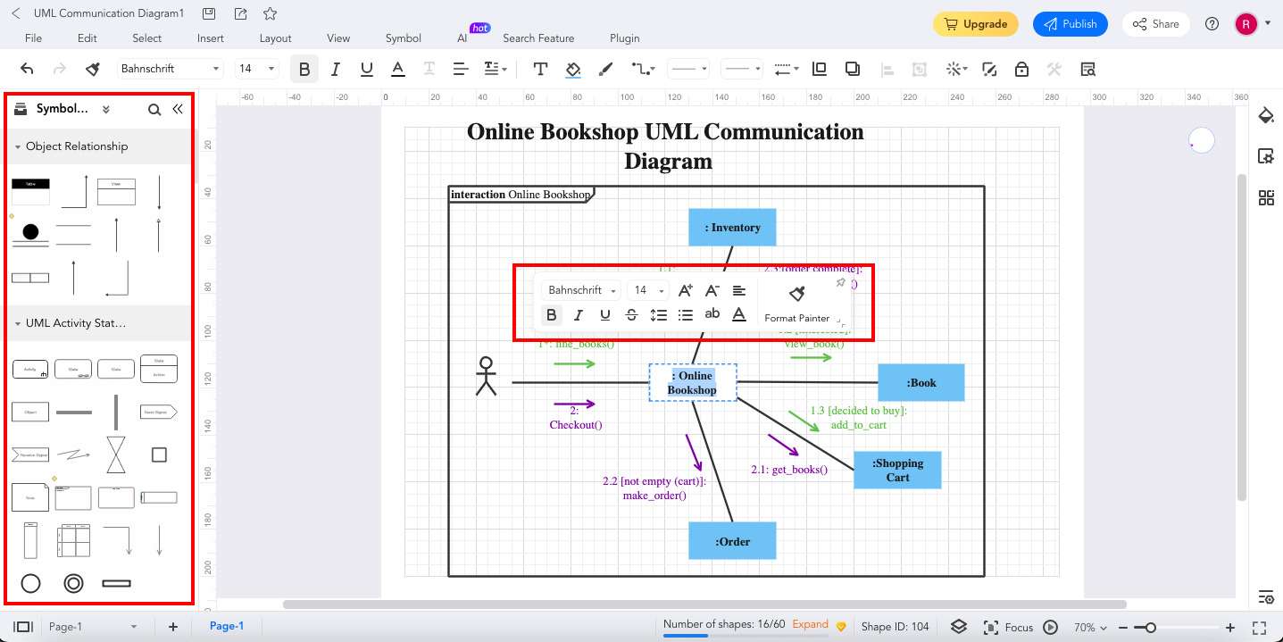
Now, it's time to customize your chosen template. EdrawMax's user-friendly interface allows you to drag and drop elements from the Symbols section onto your canvas. No need to be a tech genius – it's straightforward! You may click a topic in the template to edit the text.
Step 6Export & Share
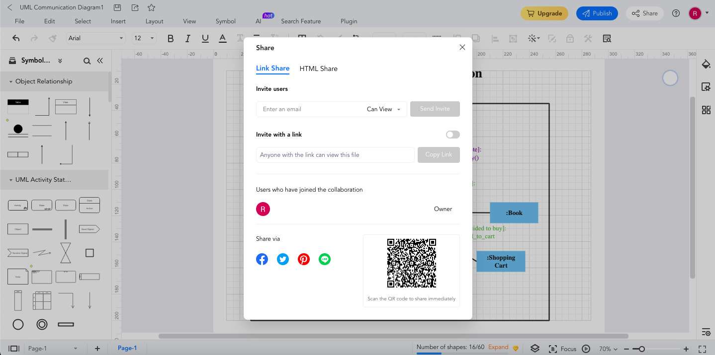
After finishing your UML diagram, you can easily Export it and send it to your coworkers or clients. Furthermore, you may Share your work on other social media sites, including Facebook, Twitter, LinkedIn, and Line.
Conclusion
UML diagrams are powerful tools that can help you understand complex systems. This article lets you explore 20 easy-to-understand UML diagram examples. UML diagrams can be your secret weapon in software design and beyond.
You also learned how EdrawMax simplifies creating and customizing UML templates. EdrawMax's user-friendly interface and extensive library of templates and symbols make it the go-to tool for diagram customization. Whether a beginner or an expert, you'll find it incredibly easy to create UML diagrams that perfectly represent your ideas and concepts in EdrawMax.